CODE
Arduino Remote Router
Most television remotes work by sending signals via an infrared LED at a certain carrier frequency. The receiver of these signals uses a device that decodes theses signals and outputs a stream of data. I found a library that made reading these signals trivial. Combining these two I felt confident I could come up with something to allow easy control of either television.
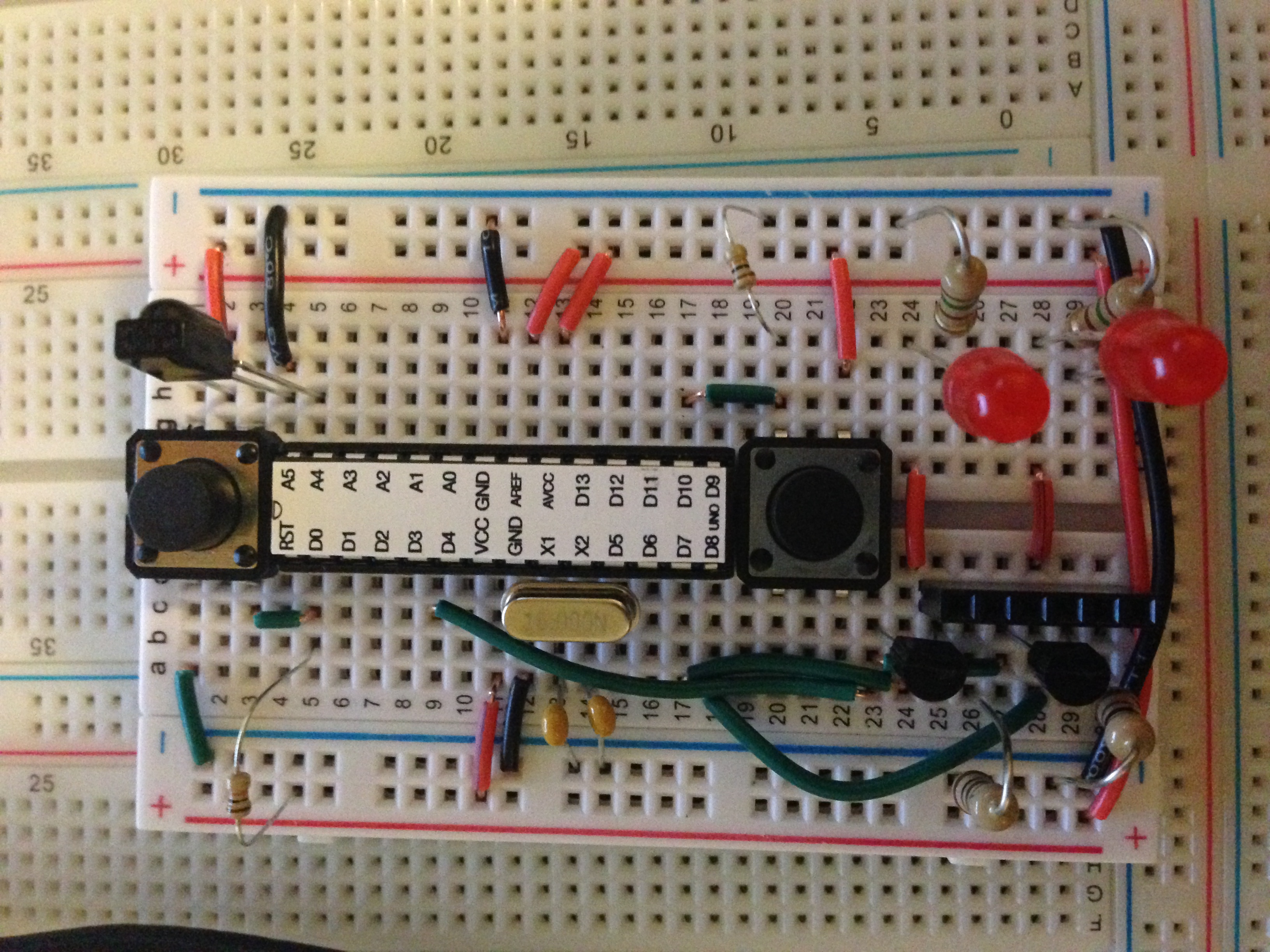
After ordering a couple infrared LEDs and the above receiver diode from Sparkfun, I threw together a prototype. This prototype was awesome in that I could both receive and transmit signals and control my television from the arduino, but the IR remote library had some limitations.
At this point it would be helpful to outline exactly what I was looking to do with this device, as without that understanding the limitations would not be apparent. I needed a device that would receive signals from a remote, which would then route those signals to either or both of two televisions. It would need to have the ability to change which televisions the signal was routed to, and a way to assign that switching to a button on the remote. Driving two IR LEDs would be the issue.
Communicating via IR requires very precise timing. Signals travel with a carrier frequency of 38 kHz to prevent ambient light from registering as a signal, and a 38 kHz signal has a period of around 27 microseconds. Usually timing is handled by the delay() function on the arduino, but this would be too imprecise. The IR remote library solves this by using the PWM timing circuit, which is much more precise. I’m not familiar with the specifics of the different PWM circuits on the Atmega328, the microcontroller at the heart of the arduino, but suffice it to say the library is written such that only one pin can act as output. I was going to have to use some sort of transistor switching to send this signal to multiple LEDs.
I’m using an output pin on the collector of two NPN transistors with 2 pins on the arduino able to set the bases of each transistor to 5V. While an oversimplification, it’s helpful to think of these as voltage controlled switches – apply a voltage through the base and the signal will pass, otherwise it will act as an open circuit. The arduino pins powering the bases of the transistors also power two LEDs which let the user know which IR LED will be transmitting the signal.
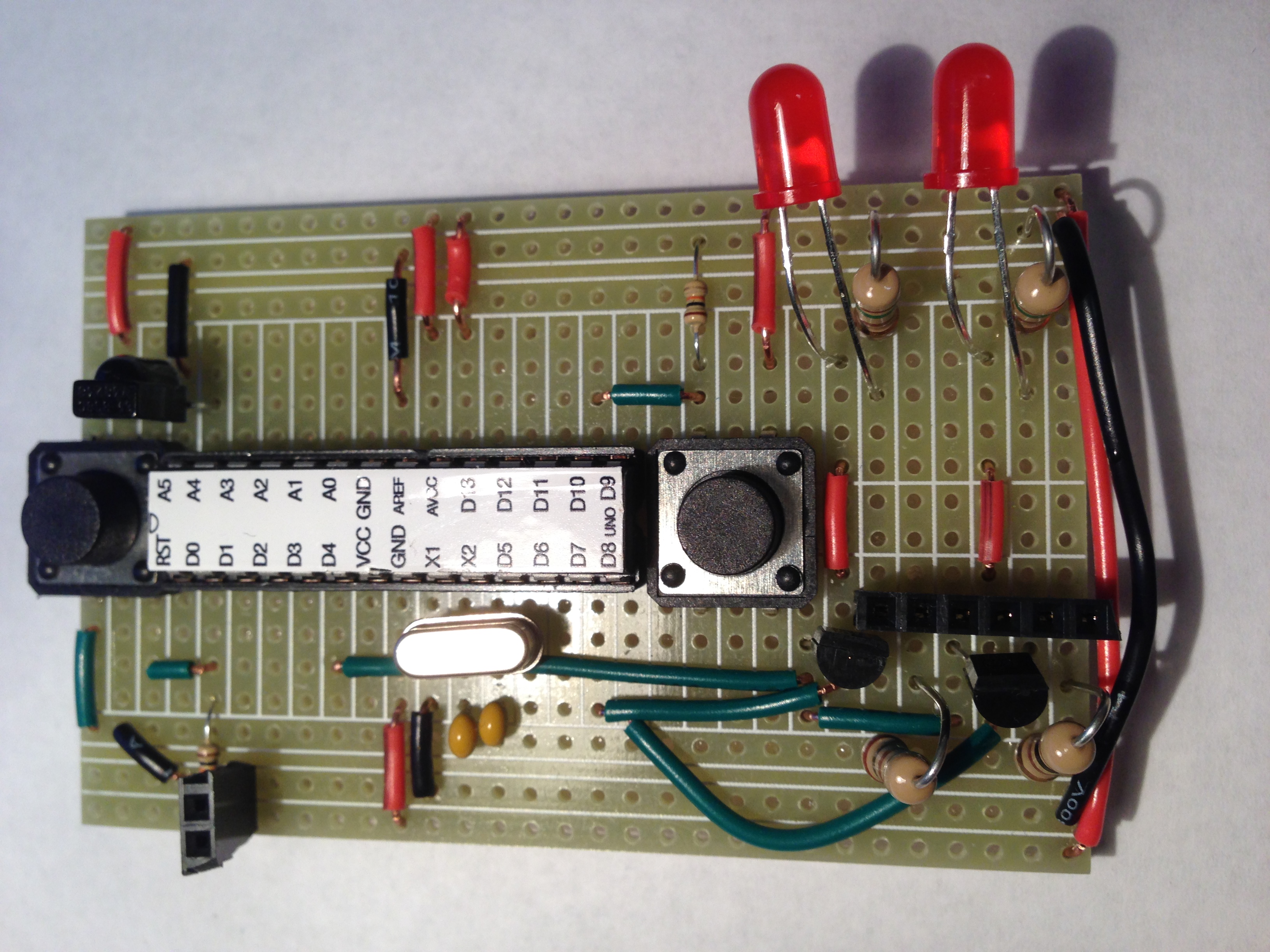
I had toyed with the idea of getting a PCB printed for this project, but that was likely going to be both expensive and unnecessary, so I decided to just use a piece of protoboard. The finished circuit is shown below. Since there wasn’t any room to drill mounting holes on the board I decided to just use some silicone to attach the board to piece of acrylic.
The installation was pretty easy, as all I had to do was solder the two IR LEDs to some wire and tape them in front of the IR sensors on the TVs. I used some aluminum foil over the LEDs so that the only signal they saw was from the router and not the remotes themselves. I powered the device with a broken USB cable that I cut the end off of, which was the easiest way I could think of to get 5V to the board without using any voltage regulators.The software was pretty simple, and the code can be found here on github. The device stores the toggle button on the remote in EEPROM so you don’t have to set it each time the device is powered on, and the rest of the code is an altered version of the IRrecord sketch from the IRremote library. It seems to work pretty well, and the only slight annoyance that had to be fixed was the board would randomly reset causing a bright light in the middle of the night. If I had to do it again I would have added in headers to make it easier to reprogram the atmega without having to take it out of the socket, but overall I’m really happy with how it turned out.